TiLDA MKe: Difference between revisions
(→blink.ino: fix pre/code tags) |
(Fix link to FreeRTOS page) |
||
| Line 131: | Line 131: | ||
==Programming the badge in FreeRTOS== | ==Programming the badge in FreeRTOS== | ||
[[TiLDA_MKe/FreeRTOS See this page for information on howto program your badge using FreeRTOS]] | [[TiLDA_MKe/FreeRTOS|See this page for information on howto program your badge using FreeRTOS]] | ||
==Contribute== | ==Contribute== | ||
Revision as of 21:41, 22 May 2016
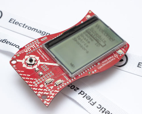
EMF 2014 Badge
The main aim of the 2014 badge is to give camp attendees an interesting bit of hardware to play with during the camp and experiment with afterwards. We designed an Arduino compatible platform to allow easy reuse and access, and have published all code and design files.
Battery Warning
A very last minute battery (and connector) change on the badge due to a supplier problem meant two issues arose with the badge during EMF:
- Always make sure to plug your battery in the right way round! The new battery connector allows you to connect it backwards. We did our best to mitigate this, but connecting it incorrectly will destroy the power management controller and prevent the badge from charging or running from the battery. It will still function perfectly using USB power. "Red" and "Black" are written next to the connector - please make sure to plug it in correctly.
- Be careful not to short the battery connector wires! The new battery connector slightly exposes the wires when the battery is plugged in. If a metal object shorts the two wires, it can result in extreme battery damage. If we'd known this was such an issue before the event we would have applied protective material to it - we suggest covering the exposed connector in tape, sugru, blu-tack, or some other insulating material. Alternatively, simply unplug the battery when your badge is not in use!
My badge is broken!
Due to the aforementioned supplier issues it is possible that you may have received a faulty badge, or it may have been damaged by connecting the battery backwards. If you badge will not turn on when it has been plugged in with a MicroUSB cable (and the power switch on the back is set to "USB"), or something else seems wrong with it, please email badge@emfcamp.org and we'll try to fix or replace your badge.
The Hardware
The badge has a plethora of hardware built in for you to play with, everything from accelerometers and gyroscopes to hidden ethernet headers! Breaking it all down is too much detail for this document, however we'll call out some things we built in that you might want to play with.
Remember the badge is Arduino Due compatible, and we broke out nearly all the features of the ARM chip so you can access them. Anything the Due can do, the TiLDA can do!
Interesting things to play with
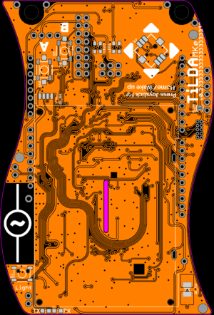
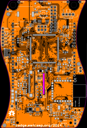
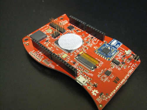
Most of the interesting things are on the back of the badge. They're clearly marked in white. This diagram of the back should allow you to locate them. Some of the following require extra parts to be added to your badge.
- Full Arduino R3 shield compatible pins (Requires soldering the headers on the back of the badge)
- Pins either side of the lanyard holes for conductive thread (D19, D18, GND, 3V3)
- Infrared transmitter on the front (Pin shortcut IR_TX_PWM)
- Infrared receiver on the front (Pin shortcut IR_RX, Part Vishay TSOP75238TT available from digikey and Farnell )
- Piezo buzzer (Pin shortcut PIEZO or PIEZO_PWM)
- On-board ethernet (not available on the Due) - requires breakout module (eBay: Elechouse Taijiuino Ethernet PHY DM9161 Module)
- MPU-6050 3-axis Accelerometer and 3-axis gyro (IMUTask.cpp and the MPU6050 library)
- 128x64 pixel backlit LCD display (JHD12864, see here for docs)
- Ciseco SRF Radio
- 1 megabit flash module (Part S25FL216K0PMFI011)
- 2x RGB LEDs on the front
Some features are not mentioned here, or optional extras. They can be found in the TiLDA_MKe/Full_Specification
The Software
Basic post-event features
We made sure that the badge has a few features to play with once the event is over. More will be added over time as attendees submit changes to us.
- Torch mode - Press the light button next to the screen. It will only light up fully if it's hung upside down to avoid blinding
- Snake
- Tetris
But of course the point of the badge is to modify it and use it for other interesting things! The following sections describe how to update the firmware on the badge, how to use it as a simple arduino, and how to write your own code for the main badge firmware.
Getting help
The EMF 2014 badge is a complex piece of hardware and software, however remember that you can just treat it as an Arduino if you find it all too daunting.
If you get stuck and need advice, there's an active IRC chatroom you can join to ask for advice, or if you're really stuck you can email us on badge@emfcamp.org.
How to update the badge software
The badge software has been substantially updated since EMF, fixing bugs and removing features that will no longer work now you're away from our radio network. You should update your badge before starting to play with it any further. If you've never used an Arduino before this might be tricky - ask an Arduino-literate friend to help you, or drop by your nearest hackspace and ask for advice.
The badge is Arduino Due compatible, so some of their instructions may help you if you have problems.
Set up your environment
- Plug your badge into your computer via a MicroUSB cable. Make sure the power switch on the back is set to "USB".
- Download the newest version of the Arduino IDE from http://arduino.cc/en/main/software
- Download the TiLDA firmware code from https://github.com/emfcamp/Mk2-Firmware
- Start the Arduino IDE.
- Now you have to change the sketchbook-folder to be the folder you just cloned or downloaded. To do this use File -> Preferences -> “Set Sketchbook location”. On MacOS, this is Arduino -> Preferences.
- Restart the Arduino IDE.
- Open sketch “EMF2014”.
- Set Tools -> Board to MKe v0.333 (RTOS Core).
- Set Tools -> Port to correct port for the Arduino
- On MacOS this is will start /dev/tty.usbmodem with 4 digits, and change for each port
- On Linux this is usually /dev/ttyACM0 but may be a higher number if you have other USB Serial devices
- Hit the upload button
- Wait
- Your badge should now be running the latest TiLDA firmware!
Programming the badge as an Arduino
The badge is completely Arduino Due compatible, simply set the board type to "MKe v0.333(Arduino Core)" upload normal Arduino code and the badge will function.
If you program the badge with simple Arduino code, you can always revert to the official firmware. Simply change the sketch to "EMF2014", and set the board type to "MKe v0.333 (RTOS Core)") and upload.
blink.ino
Here is a tweaked version of the standard blink sketch that will flash the RX and TX LEDs
  void setup() {
    pinMode(PIN_LED_TX, OUTPUT);
    pinMode(PIN_LED_RX, OUTPUT);
  }

  void loop() {
      digitalWrite(PIN_LED_TX, HIGH);
      digitalWrite(PIN_LED_RX, LOW);
      delay(1000);
      digitalWrite(PIN_LED_TX, LOW);
      digitalWrite(PIN_LED_RX, HIGH);
      delay(1000);
  }
- TODO ADD LINK TO PIN MAPPING NAMES/DEFINITIONS
Writing to the Screen
- TODO
Reading from the Accelerometer
- TODO
Reading the Battery Voltage
- TODO
Controlling the LEDs
- TODO
Reading Button & Joystick Input
- TODO
Buzzer?
- TODO
Using the Radio to Send and Receive Data
- TODO
Arduino Gotchas
- Most Arduino code out there use Serial not SerialUSB. On MKe Serial is wired to the SRF radio. When using example code do a find and replace for Serial/SerialUSB this will redirect the Serial traffic of the USB port
- If you want to send data over the Radio you need to wake it and enable it first, set SRF_SLEEP to LOW using the following two lines of code
pinMode(SRF_SLEEP, OUTPUT); digitalWrite(SRF_SLEEP, LOW);
Programming the badge in FreeRTOS
See this page for information on howto program your badge using FreeRTOS
Contribute
Send us a pull request via GitHub - We’ll do our best to review and merge the good ones so others can use them.
Cool Hacks!
3d printable & laser-cuttable badge case
3d print-able and laser-able case files here
Making the badge Arduino shield compatible
To make the badge Arduino shield compatible you'll need to solder simple strips of header pins onto the back of the badge. You need the following headers
| Qty | Type | Use | Rapid part |
|---|---|---|---|
| 1 | 2x03 Male | SPI | |
| 2 | 1x08 Female | Power, Analog pins | |
| 2 | 1x10 Female | Digital pins | |
| 1 | 2x08 Male | Ethernet |
The picture to the right shows the placement.
Source
All the source code and designs are on openly available on Github:
- Hardware - the full board design
- Documentation - a dump of relevant parts datasheets
- Firmware - source code for the badge software
- Software - server-side software for the network
If you want to help, point your IRC client to #tilda on Freenode.


